Sequence Diagrams — How Objects Interact Over Time
Introduction
A class diagram shows you the structure — what classes exist and how they're related. But it tells you nothing about what happens at runtime. When a member borrows a book, which object calls which method? In what order? What gets returned?
A sequence diagram answers these questions. It shows a specific scenario — a single path through the system — as a conversation between objects over time. Each object has a vertical lifeline, and horizontal arrows show the messages (method calls) flowing between them.
Think of it like a movie script. A class diagram is the cast list — it tells you who the characters are. A sequence diagram is a scene from the screenplay — it shows exactly who says what, in what order, and what happens as a result.
In LLD interviews, you'll draw sequence diagrams to answer questions like: "Walk me through what happens when a user places an order" or "How does the borrowing flow work?" The interviewer is testing whether you understand how objects collaborate — not just what they contain.
This is one of the most powerful UML diagrams for design. Most bugs in object-oriented systems happen at the interaction boundaries — one object calling the wrong method, at the wrong time, with the wrong data. A sequence diagram makes these interactions explicit.
We'll model the book borrowing flow in our Library Management System — the same domain from the previous tutorials.
Anatomy of a Sequence Diagram
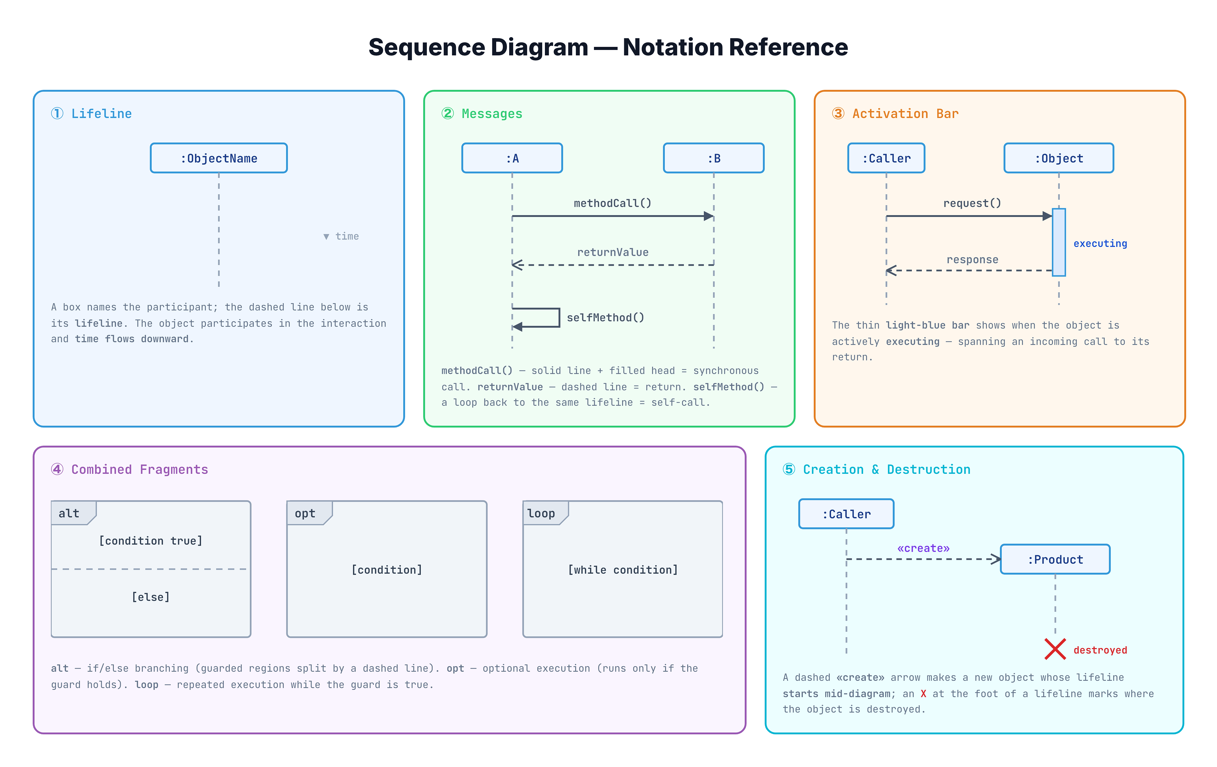
A sequence diagram has five key elements:
1. Lifelines (Vertical Dashed Lines)
Each object (or actor) in the scenario gets a vertical dashed line extending downward. The object's name and class are shown in a box at the top: :Member, :LoanService, :Book.
Time flows downward — messages at the top happen first, messages at the bottom happen last.
2. Messages (Horizontal Arrows)
Messages are method calls between objects, drawn as horizontal arrows from the caller to the receiver.
- Synchronous message (solid arrow, filled arrowhead): The caller waits for a response. This is a normal method call. Example:
:Member→:LoanService:borrowBook(bookId) - Return message (dashed arrow): The response coming back. Example:
:LoanService→:Member:loan(dashed arrow going back) - Self-call (arrow looping back to the same lifeline): An object calling its own method. Example:
:LoanServicecallsvalidateMember()on itself.
3. Activation Bars (Thin Rectangles)
Activation bars are thin rectangles overlaid on a lifeline. They show when an object is actively processing — executing a method. The bar starts when a message arrives and ends when the return message is sent.
4. Combined Fragments (Boxes with Labels)
To show conditional logic or loops, sequence diagrams use combined fragments — labeled rectangular boxes surrounding a group of messages:
alt(alternative): If/else logic. The box is divided by a dashed horizontal line — the top section is the "if" case, the bottom is the "else" case.opt(optional): Code that only executes under a condition. Likealtwith no else branch.loop: Messages that repeat. The guard condition specifies when to continue.
5. Object Creation and Destruction
- Creation: A dashed arrow labeled
<<create>>points to the new object's lifeline box (which appears at the point of creation, not the top). - Destruction: An
Xat the bottom of a lifeline marks when the object is destroyed.
Notation Guide
Visualization
Complete Example — Book Borrowing Sequence
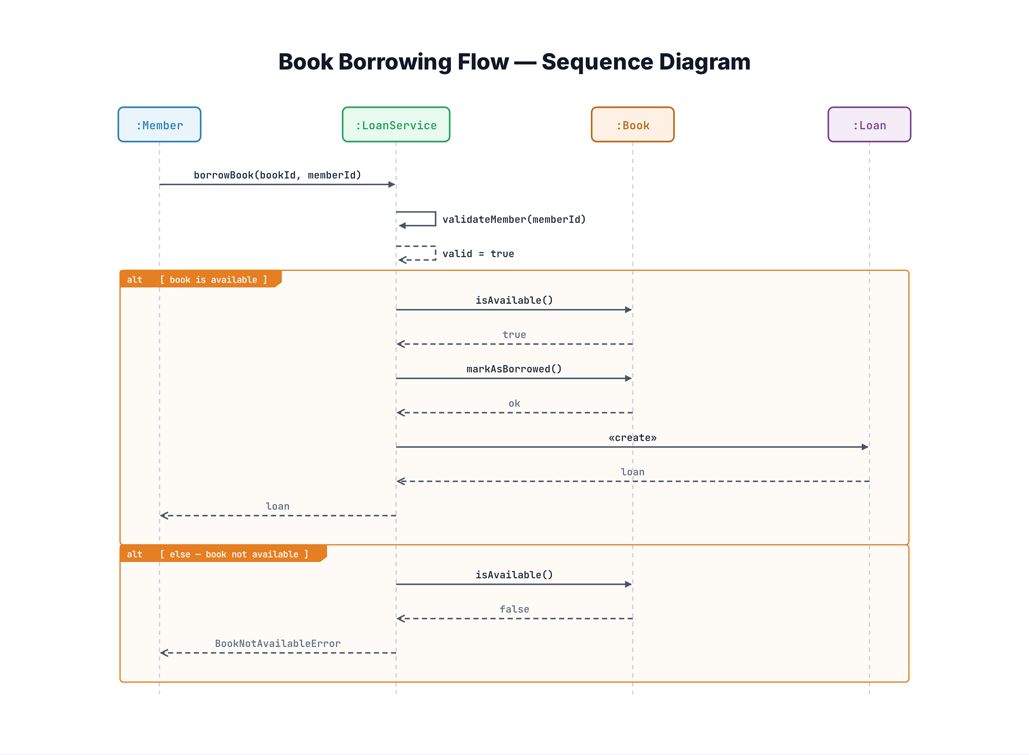
Here's the complete sequence diagram for borrowing a book. Read it top-to-bottom — each horizontal arrow is a method call, and time progresses downward:
Happy path (book available):
MembercallsLoanService.borrowBook(bookId, memberId)LoanServicevalidates the member (self-call tovalidateMember())LoanServiceasksBook.isAvailable()→ returnstrueLoanServicecallsBook.markAsBorrowed()LoanServicecreates a newLoanobject with the book, member, and due dateLoanServicereturns theLoantoMember
Alternate path (book unavailable):
- At step 3, if
Book.isAvailable()returnsfalse,LoanServicereturns an error — no Loan is created.
Notice how this sequence diagram tells a story that the class diagram (from the previous tutorial) cannot — it shows the order of operations and the conditional branching. The class diagram shows that LoanService, Book, and Loan exist and are related. The sequence diagram shows how they interact for a specific use case.
How to Read a Sequence Diagram
Reading Order
- Start at the top-left — identify the actor or object that initiates the scenario
- Read downward — follow messages chronologically, like reading a comic strip
- Follow the arrows — solid arrows going right are calls; dashed arrows going left are returns
- Watch activation bars — they tell you which object is "in control" at any moment
- Note combined fragments —
alt,opt, andloopboxes show branching and repetition
Translating to Code
Every sequence diagram maps directly to method calls. The borrowing sequence translates to:
member.borrowBook(bookId)        →  1. Entry point
  loanService.borrowBook(...)    →  2. Delegation
    loanService.validateMember() →  3. Self-call
    book.isAvailable()           →  4. Query
    if available:
      book.markAsBorrowed()      →  5. State change
      new Loan(book, member)     →  6. Object creation
      return loan                →  7. Return
    else:
      throw error                →  8. Alt path
This is why sequence diagrams are so valuable — they ARE the algorithm for a use case, expressed visually. In an LLD interview, drawing this diagram IS designing the interaction logic.
Common Mistakes in Sequence Diagrams
Mistake 1: Too Many Lifelines
❌ Wrong: Including 10+ objects in one diagram, making it horizontally unreadable with crossing arrows.
✅ Right: Keep sequence diagrams focused on one scenario with 3-6 lifelines. If a use case involves more objects, split into multiple diagrams — one for the "happy path" and one for error handling.
Mistake 2: Missing Return Messages
❌ Wrong: Drawing arrows going right (method calls) but never showing what comes back.
✅ Right: Every synchronous call should show a dashed return arrow with the return value. This forces you to think about what each method actually returns — a design insight you might miss otherwise.
Mistake 3: Showing Internal Implementation Details
❌ Wrong: Five self-call arrows on LoanService showing parseISBN(), trimWhitespace(), validateFormat(), lookupCache(), queryDatabase().
✅ Right: Show only the design-level interactions. A self-call like validateMember() communicates the intent. Internal implementation details clutter the diagram without adding design value.
Mistake 4: No Combined Fragments for Branching
❌ Wrong: Drawing two completely separate sequence diagrams — one for "book available" and one for "book unavailable" — when they share 80% of the same flow.
✅ Right: Use an alt fragment to show both paths in one diagram. This communicates the decision point and both outcomes clearly.
Mistake 5: Confusing Arrow Direction
❌ Wrong: Drawing a return arrow from :Member back to :LoanService — implying the member calls the service back.
✅ Right: Return arrows always go from the callee back to the caller — from :LoanService to :Member. The callee performed the work and is returning the result.
When to Draw Sequence Diagrams
Draw a sequence diagram when:
- An interviewer asks "walk me through the flow" — this is a direct request for a sequence diagram
- You need to show how multiple objects collaborate for a specific use case
- The interaction order matters and could lead to bugs if wrong
- You want to verify your class responsibilities — if an object receives a message it can't handle, your class design is wrong
Don't draw a sequence diagram when:
- You need to show all features of a system — use a use case diagram instead
- You need to show the overall structure — use a class diagram instead
- The flow is trivial (one object calls one method on another) — just explain it verbally
Interview tip: Draw the sequence diagram for the most complex scenario in the system. For a Library System, that's the borrowing flow. For a Parking Lot, that's the vehicle entry flow. This shows the interviewer that your objects collaborate correctly and that your class responsibilities make sense.
You'll combine class diagrams with sequence diagrams extensively in the Design Problems course — especially for systems like the Parking Lot, Elevator, and Ride-Sharing Service where object interactions are the heart of the design.
Key Takeaways
- A sequence diagram shows how objects interact for a specific scenario — time flows downward, each object has a vertical lifeline, and horizontal arrows represent method calls
- Solid arrows (filled arrowhead) = synchronous calls; dashed arrows = return values; self-call loops = object calling its own methods
- Activation bars (thin rectangles on lifelines) show when an object is actively executing a method
- Combined fragments handle logic:
altfor if/else,optfor optional behavior,loopfor iteration - Object creation is shown with
<<create>>— the new object's lifeline starts at the creation point, not the top - In LLD interviews, sequence diagrams prove that your class design actually works — that objects can collaborate correctly to fulfill a use case
- Keep diagrams focused: one scenario, 3-6 lifelines — split complex flows into multiple diagrams rather than creating an unreadable mega-diagram